Get notified the moment we go live on Kickstarter. Claim your Super Early Bird rewards, redeem your deposit benefits, and receive the latest product updates.
by Brett | Jul 20, 2026
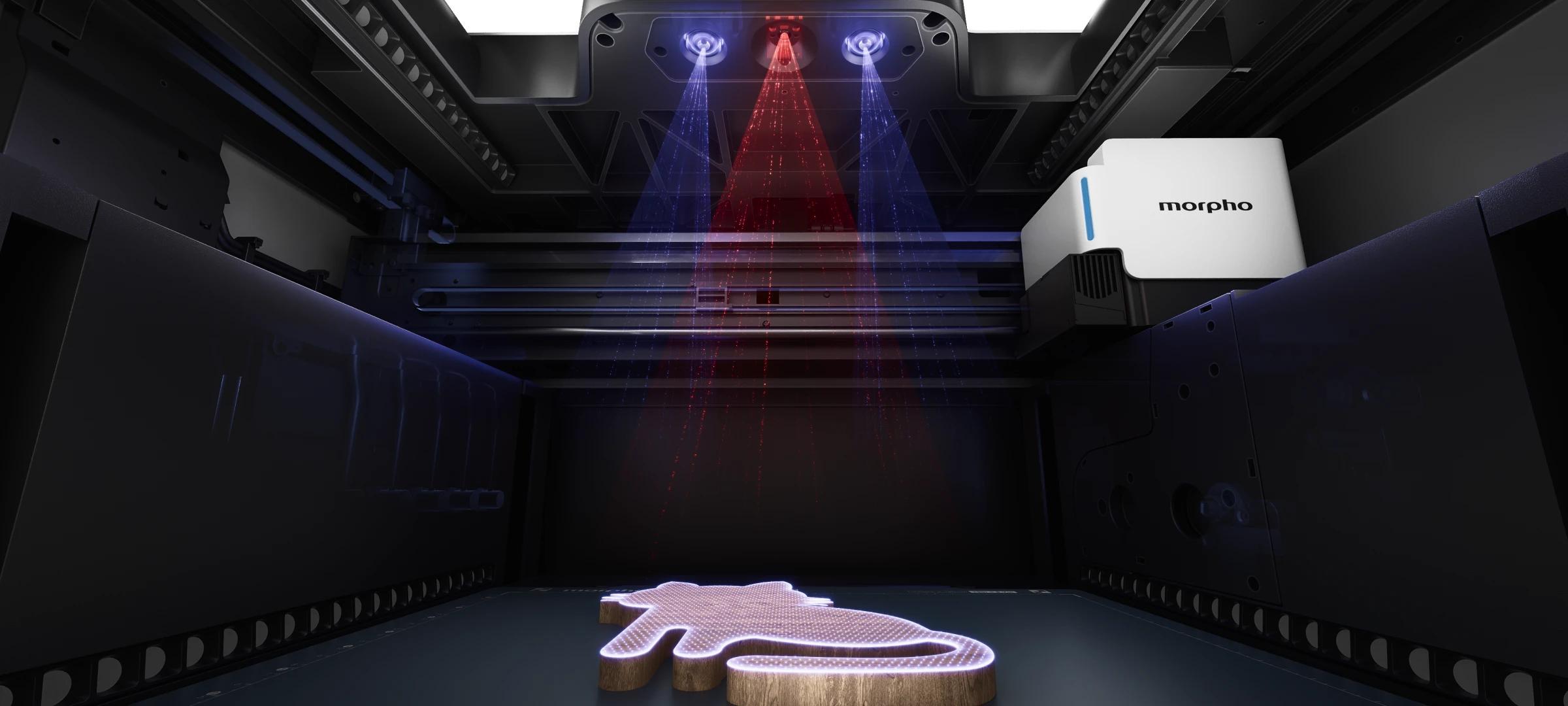
If you have used an industrial UV printer before, you probably know that alignment can be one of the most annoying parts of the workflow.
The traditional way is often very manual. You first print a positioning guide or an outline on the printbed. Then you place your phone case, acrylic sheet, card, box, or whatever object you are printing onto that printed position.
It works, but it is easy to make mistakes.
You need to print the guide first, which already wastes some ink. Then you need to place the object very carefully. If your hand moves a little, or the object is not perfectly aligned with the guide, the final print will shift. Many failed prints are not caused by the artwork or the printer’s print quality. They happen because alignment went wrong before the print even started.
Another way is to measure the object and its position manually, then enter the coordinates in software. Experienced users can do this, but it still depends heavily on human operation. A small measuring error, a slightly tilted object, or a forgotten offset can all show up in the final result.
So alignment may look like a small step, but it affects time, ink, success rate, and also how much trust users have in the machine.
In some industrial workflows, there are other solutions. Some UV printers use CIS technology, which is similar to the linear scanning structure inside copiers or scanners. It scans across the printbed and captures the position of the objects.
For very fixed production scenarios, CIS can work. For example, if you are always printing the same acrylic sheet at the same height, the workflow can be standardized.
But desktop UV printing is usually not like that.
Today you may print a phone case. Tomorrow it may be a fridge magnet. The day after that, it may be a small box. The objects can have different heights, colors, edges, and materials.
CIS has one major limitation: its depth of field is very shallow. Think about a copier. When you copy an ID card, the card needs to sit flat against the glass. If you lift it even a little, the image quickly becomes blurry or hard to capture. That is why CIS can run into limitations when the objects are irregular or have different heights.
Some consumer-level products use a single camera to help with alignment. This is more convenient than measuring everything by hand. The camera takes a photo, the user sees what is on the printbed, and then drags the artwork roughly onto the object in software.
But the biggest problem with a single camera is that it does not have real depth information. It is a bit like closing one eye and trying to grab a water bottle on the table. You can still see the bottle, but your sense of distance becomes worse. Your hand may still reach it, but it is easier to be slightly off. A machine has a similar problem. A single camera only sees a 2D image. Once the object has height, lens distortion, perspective error, or slight placement changes can all create offset. It may look aligned on the screen, but the actual print can still shift.
Morpho’s Smart Alignment uses stereo vision.
There are two cameras at the top of the machine, similar to a left eye and a right eye. The left camera and the right camera look at the same object from slightly different positions. Because of that, the same point appears in slightly different positions in the two images. By calculating this difference, the system can estimate how far the object is from the cameras. In other words, it can understand height and spatial position. The principle is very similar to human vision.
We judge distance, pick up objects, and avoid obstacles largely because of stereo vision. Humans and many mammals developed this spatial perception system through a very long process of evolution. It is a very robust way to understand the physical world.
For UV printing, this matters a lot.
UV printing is not only about printing on a flat sheet of paper. Users place all kinds of objects into the machine: phone cases, acrylic pieces, wood sheets, fridge magnets, small boxes, and sometimes irregular objects. They may have different heights, colors, surfaces, and edges.
Morpho first uses the left and right cameras at the top of the machine to capture the printbed. The system uses stereo vision to estimate the height and spatial position of the object. This process is fast. In many cases, height measurement can be completed in under a second.
Once the machine has height information, it is no longer looking at just a flat photo. It starts to understand where the object is high, where it is low, and where the boundary is likely to be. Combined with the 2D image and a pre-trained recognition model, the system can better understand what the object may be, such as a phone case, a fridge magnet, or another common object.
This is the foundation of Morpho’s Smart Alignment.
It is not just taking one photo and asking the user to drag artwork by feeling. The machine first understands the object’s position in 3D space, then uses that information for alignment.
This also reflects how we think about product design at Morpho.
Physics First is an important part of Morpho’s company culture, and it is one of our basic beliefs when building products. When we face a problem, we try to look at the root cause first.
Alignment may look like a software problem, or a user operation problem. But if you go one layer deeper, it is really a spatial measurement problem. Where is the object? How tall is it? Where is the edge? What is the distance between the printhead and the surface?
If the machine does not know these things, the user has to compensate with printed guides, rulers, manual placement, and rough positioning on a screen. That can work, but it is not a great experience, and it is easy to get wrong.
That is why we chose stereo vision. We did not choose it just because it sounds like a fancy feature. We chose it because desktop UV printing really needs the machine to understand 3D space.
We also ask our engineers to think about failure modes before finalizing a design. Where might this design fail? Under what conditions might it become inaccurate? If it becomes inaccurate, will the user waste material or ink?
Alignment is a good example. If users have to guess, measure, and test everything by themselves, there are many ways things can go wrong. The object may be placed slightly off. The printed guide may not be perfectly aligned. A camera without depth information may introduce offset.
What we want Morpho to do is to let the machine understand as much of this as possible. Of course, making stereo vision work reliably inside a compact desktop machine is not easy. Real users will put in all kinds of objects, with different colors, heights, reflectivity, edge shapes, and surface materials. Each of these can create new corner cases.
We are still continuously iterating on this system. More testers and reviewers in the industry will receive machines later, and more real-world reviews will come out. Then everyone will be able to see how Morpho performs across different materials, objects, and workflows.
Please stay tuned.
